What is a TLOC?
- Transport Locators, or TLOCs, are the attachment points where a WAN Edge router connects to the WAN transport network.
- A TLOC is uniquely identified and represented by a three-tuple, consisting of
- System-IP: The
System-IP is the unique identifier of the WAN edge device across the SD-WAN
fabric. It is like the Router-ID in traditional routing protocols such as BGP.
It does not need to be routable or reachable across the fabric.
- Transport Color: The
color is an abstraction used to identify different WAN transports such as MPLS,
Internet, LTE, 5G, etc. In scenarios where transport types are duplicated (for
example two different Internet providers) and should be treated differently
from each other, the colors could be arbitrary, such as Green, Blue, Silver,
Gold, etc.
- Encapsulation Type:
This value specifies the type of encapsulation this TLOC uses - IPsec or GRE.
To successfully form a data plane tunnel to another TLOC, both sides must use
the same encryption type.
- TLOC routes are advertised to vSmarts via OMP, along with a number of attributes, including the private and public IP address and port numbers associated with each TLOC, as well as color and encryption keys.
- These TLOC routes with their attributes are distributed to other WAN Edge routers.
- Now with the TLOC attributes and encryption key information known, the WAN Edge routers can attempt to form BFD sessions using IPsec with other WAN Edge.
 .
.
What is TLOC Color?
- TLOC Color is a logical abstraction used to identify
specific WAN transport that connects to a WAN Edge device.
- The color is a
statically defined keyword that distinguishes a particular WAN transport as either
public or private and is globally significant across the Cisco SD-WAN fabric.
- From the perspective of vEdge-1, the only way to distinguish
which interface is connected to which cloud is through the concept of colors
that would be externally defined by the controller or locally via CLI.
The TLOC color is configured per interface under the
transport vpn0/ interface / tunnel-interface settings as in is shown below:
vpn 0
interface ge0/0
ip address 10.1.1.43/24
tunnel-interface
encapsulation ipsec
color mpls
As of now, there are 22 pre-defined color keywords, and they
are divided into two main categories - public and private colors.
- The public colors are designed to distinguish connections
to public networks such as the Internet where typically the attachment
interface has an RFC1918 address that is later translated to a publicly
routable address via NAT.
- On the other
hand, private colors are intended for use on connections to clouds where NAT is
not utilized. On WAN Edge routers, each Transport Locator is associated with a
private-public IP address pair.
The TLOC color dictates whether the private
or public IP address will be used when attempting to form a data plane tunnel
to a remote TLOC.
Communication Between Colors
- During the authentication process with the vBond
orchestrator, WAN edge devices learn whether they sit behind a NAT device and
what is their NATed address and port.
- This is done using the STUN protocol and the process is
explained in further detail as below TLOCs and NAT.
- In the end, each TLOC contains a pair of private/public
addresses and ports.
- If there is no NAT, both the private and public addresses
are the same, if there is a NAT device along the path, the private address
represents the native interface IP and the public address represents the
post-NAT address.
- When two Cisco SD-WAN devices attempt to form an overlay
tunnel between each other, they look at the colors at both ends to decide which
IP address to use.
- If the TLOC color at both ends is a Public one, the WAN
edge devices attempt to form the data plane tunnel using their public IP
addresses.
The following diagram demonstrates the general behavior. These rules apply to:
- WAN Edge routers using IPsec to other WAN Edge routers
- DTLS/TLS connections between WAN Edge routers and vManage and vSmart controllers
- DTLS/TLS connections between vManage and vSmart controllers
TLOC
Carrier
- However,
specific scenarios might occur where using the public IP addresses between
private colors is the desired behavior.
- An example would be having two MPLS
clouds that are interconnected using NAT.
- For such cases, there is a particular
TLOC attribute called carrier that changes this behavior - if the carrier
setting is the same in the local and remote TLOCs, the WAN edge device attempts
to form a tunnel using the private IP address, and if the carrier setting is
different, then the WAN edge device attempts to form a tunnel using the public
IP address.
- The diagram below visualizes this:
TLOC Color Restrict
- By default, WAN edge routers try to form overlay tunnels to
every received TLOC from a different site using every available color.
- This is
usually the desired outcome in scenarios where we have two Internet connections
from two different providers.
- Although we typically mark them with different
colors to treat them separately, we would like to have a full mesh of tunnels
because there is IP reachability between the clouds.
- However, this behavior might not be desirable in scenarios
where we have one private transport alongside an Internet cloud, as it could
lead to inefficient routing—such as WAN edge routers trying to build tunnels
through the MPLS cloud to Internet TLOCs.
- Even though the IP reachability
between the clouds may exist, the tunnels might be established over paths that
are inefficient or unintended.
- This behavior can be changed with the restrict
keyword or by using tunnel groups.
vpn 0 interface ge0/0 ip dhcp-client tunnel-interface encapsulation ipsec color mpls restrict
When a TLOC is marked as
restricted, a WAN edge route router will attempt to establish a data plane
tunnel to a remote TLOC only via WAN connections marked with the same color.
This behavior is demonstrated in below figure. vEdge-1 will never try to
establish an IPsec tunnel from T1 to T4 because TLOC1 and TLOC4 are not marked
with the same color.
Another option to achieve the same
goal of restricting the data plane connectivity between the same colors is by
using tunnel groups. Only tunnels with matching tunnel groups will form a data
plane connection (regardless of the color).
vpn 0
interface ge0/0
ip dhcp-client
tunnel-interface
encapsulation ipsec
group 199
Bidirectional Forwarding Detection (BFD)
- On Cisco WAN Edge routers, BFD is automatically started between peers and cannot be disabled.
- It runs between all WAN Edge routers in the topology encapsulated in the IPsec tunnels and across all transports.
- BFD operates in echo mode, which means when BFD packets are sent by a WAN Edge router, the receiving WAN Edge router returns them without processing them.
- Its purpose is to detect path liveliness and it can also perform quality measurements for application-aware routing, like loss, latency, and jitter.
- BFD is used to detect both black-out and brown-out scenarios.
Tunnel Liveliness
- To detect whether an IPsec tunnel is up, BFD hello packets are sent every 1000 milliseconds/1 second by default on every tunnel interface.
- The default BFD multiplier is 7, which means the tunnel is declared down after 7 consecutive hellos are lost.
- The BFD hello interval and multiplier are configurable on a per color basis.
- BFD packets are marked with DSCP 48, which is equivalent to CS6 or IP Precedence 6. Packets are placed in the low latency, high priority QoS queue (LLQ) before being transmitted on the wire but are not subjected to the LLQ policer.
- Though rarely needed, the DSCP value can be modified using an egress ACL on the WAN interface.
Path Quality
- BFD is used not only to detect blackout conditions but is also used to measure various path characteristics such as loss, latency, and jitter.
- These measurements are compared against the configured thresholds defined by the application-aware routing policy, and dynamic path decisions can be made based on the results in order to provide optimal quality for business-critical applications.
- For measurements, the WAN Edge router collects packet loss, latency, and jitter information for every BFD hello packet.
- This information is collected over the poll-interval period, which is 10 minutes by default, and then the average of each statistic is calculated over this poll-interval time.
- A multiplier is then used to specify how many poll-interval averages should be reviewed against the SLA criteria.
- By default, the multiplier is 6, so 6 x 10-minute poll-interval averages for loss, latency, and jitter are reviewed and compared against the SLA thresholds before an out-of-threshold decision is made.
- The calculations are rolling, meaning, on the seventh poll interval, the earliest polling data is discarded to accommodate the latest information, and another comparison is made against the SLA criteria with the newest data.
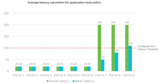
The following figure shows an example when an out-of-threshold condition is recognized when latency suddenly increases.
When latency jumps from 20 ms to 200 ms at the beginning of poll-interval 7, it takes 3 poll intervals of calculations before the latency average over 6 poll intervals crosses the configured SLA threshold of 100 ms.
- You may want to adjust application route poll-interval values, but you need to exercise caution, since settings that are too low can result in false positives with loss, latency, and jitter values, and can result in traffic instability.
- It is important that there is a sufficient number of BFD hellos per poll interval for the average calculation, or large loss percentages may be incorrectly tabulated when one BFD hello is lost.
- In addition, lowering these timers can affect overall scale and performance of the WAN Edge router.
- For 1 second hellos, the lowest application route poll-interval that should be deployed is 120 seconds.
- With 6 intervals, this gives a 2-minute best case and 12-minute worst case before an out-of-threshold is declared and traffic is moved from the current path.
- Any further timer adjustments should be thoroughly tested and used cautiously
vBond as a NAT Traversal Facilitator
- Any controller or SD-WAN router may be unknowingly sitting behind a NAT
device.
- Knowing what IP address/port to connect to from outside the network is crucial to
successfully establishing control and data plane connections in the SD-WAN
network.
- vBond plays a crucial role and acts as a Session Traversal Utilities for
NAT (STUN) server, which allows other controllers and SD-WAN routers to
discover their own mapped/translated IP addresses and port numbers.
- SD-WAN
devices advertise this information along with their TLOCs so other SD-WAN
devices have information in order to make successful connections.

NAT
Detection
Cisco SD-WAN
solution is designed to run over any kind of WAN transport that is available to
the WAN edge devices including all different public networks such as Broadband,
4G/5G, LTE, Business Internet, and so on. This implies that the overlay fabric
should be able to form through all flavors of Network Address Translations that
these public networks utilize. In practice, any Cisco SD-WAN device may be
unknowingly sitting behind one or more NAT devices. To discover the public IP
addresses/ports allocated by NAT, Cisco SD-WAN devices use the Session
Traversal Utilities for NAT (STUN) protocol defined in RFC5389.

- STUN is a client-server protocol that uses a
request/response transaction in which a client sends a request to a server, and
the server returns a response.
- As the request (called STUN Binding Request)
passes through a NAT, the NAT will modify the source IP address/port of the packet.
- Therefore, the STUN server will receive the request with the public IP
address/port created by the closest NAT device.
- The STUN server then copies the
public address into an XOR-MAPPED- ADDRESS attribute in the STUN Binding
response and sends it back to the client.
- Going back through the NAT, the
public address/port in the IP header will be un-NATted back to the private
ones, but the public address copy in the body of the STUN response will remain
untouched. In this way, the client can learn its IP address allocated by the
outermost NAT with respect to the STUN server.
NAT Types
In a typical production SD-WAN
deployment, we would probably have many remote sites connected via many
different Internet connections to a centralized data center or a regional hub.
In most regions in the world, Internet providers will always use some type of
private-public address translation due to a shortage of public IPv4 addresses.
Let's look at the NAT classifications according to the STUN protocol and how
they can affect whether sites can form connections and communicate directly
with each other or not.
Full-Cone NAT
- A full-cone is one where all
packets from the same internal IP address are mapped to the same NAT IP
address. This type of address translation is also known as One-to-One.
- Additionally, external hosts can
send packets to the internal host, by sending packets to the mapped NAT IP
address.
Restricted-Cone NAT
- A Restricted-Cone network address
translation is also known as Address-Restricted-Cone.
- It is a network
translation technique where all packets from the same internal IP address are
mapped to the same NAT IP address.
- The difference to a Full-Cone is that an
external host can send packets to the internal host only if the internal host
had previously sent a packet to the IP address of the external destination.
- It
is important to note that once the NAT mapping state is created, the external
destination can communicate back to the internal host on any port.
Port-Restricted-Cone NAT
- A Port-Restricted-Cone is like the
Restricted-Cone address translation, but the restriction also includes port
numbers.
- The difference is that an external destination could send back packets
to the internal host only if the internal host had previously sent a packet to
this destination on this exact port number.
- In a typical Cisco IOS/IOS-XE or
Cisco ASA configuration, this feature is known as Port Address Translation
(PAT).
Symmetric
- Symmetric NAT is also known as
Port Address Translation (PAT) and is the most restrictive of all other types.
- It is a network translation technique where all requests from the same internal
IP address and port to a specific destination IP address and port, are mapped
to a unique NAT IP address and NAT port.
- Furthermore, only the external
destination that received a packet can send packets back to the internal host.
- In a typical Cisco IOS/IOS-XE or Cisco ASA configuration, this feature is known
as Port Address Translation (PAT) with port-randomization.
NAT
Recommendations
- Though
several types of NAT are supported with WAN Edge routers, if full mesh traffic
is desired, take care to ensure at least one side of the WAN Edge tunnel can
always initiate a connection inbound to a second WAN Edge even if there is a
firewall in the path.
- It is recommended to configure full-cone, or 1-to-1 NAT
at the data center or hub site so that, regardless of what NAT type is running
at the branch (restricted-cone, port-restricted cone, or symmetric NAT), the
branch can send traffic into the hub site using IPsec at a minimum without
issue.
- Two sites with firewalls running symmetric NAT will have issues forming
a tunnel connection, as this NAT translates the source port of each side to a
random port number, and traffic cannot be initiated from the outside.
- Symmetric
NAT configured at one site requires full-cone NAT or a public IP with no NAT on
the other site in order to establish a direct IPsec tunnel between them. Sites
which cannot connect directly should be set up to reach each other through the
data center or other centralized site.
The
following table shows different NAT type combinations and the corresponding
IPsec tunnel status:
|
vEdge-1
|
vEdge-2
|
IPsec tunnel can form
|
GRE tunnel can form
|
|
No-NAT (Public IP)
|
No-NAT (Public IP)
|
YES
|
YES
|
|
No-NAT (Public IP)
|
Symmetric
|
YES
|
NO
|
|
Full Cone (One-to-one)
|
Full Cone (One-to-one)
|
YES
|
YES
|
|
Full Cone (One-to-one)
|
Restricted-Cone
|
YES
|
NO
|
|
Full Cone (One-to-one)
|
Symmetric
|
YES
|
NO
|
|
Restricted-Cone
|
Restricted-Cone
|
YES
|
NO
|
|
Symmetric
|
Restricted-Cone
|
NO
|
NO
|
|
Symmetric
|
Symmetric
|
NO
|
NO
|
IMPORTANT Note that for overlay tunnels configured
to use GRE encapsulation instead of IPsec, only public IP addressing, or
one-to-one address translation is supported. Any type of Network Address
Translation with port overloading is not supported since GRE packets lack an L4
header.
Data Plane Privacy and Encryption
Most overlay solutions these days encrypt and authenticate data plane
traffic using IPsec and Cisco SD-WAN is no different. Although there is one
major difference that Cisco SD-WAN utilizes in order to scale better and more
efficiently. Most traditional IPsec environments use Internet Key Exchange
(IKE) to handle the key exchange between IPsec peers. However, IKE creates
scalability issues in full-meshed environments with thousands of spokes because
each spoke is required to manage n^2 key exchanges and n-1 different keys.
- Cisco SD-WAN was designed to overcome these scaling limitations by not
utilizing IKE at all but instead implementing the key exchange within the
control plane.
- This is possible because vEdges identity is established during the
provisioning process with the vBond orchestrator.
- The main
idea is that WAN edge routers can leverage the existing encrypted control
connections to the vSmart controller and advertise their keys to the controller
via OMP.
- The
controller then redistributes them as OMP updates to all other peers, so the
exchange is completely done through the SD-WAN control plane.
vEdge-1 generates an AES-256-bit key for each connected WAN transport.
In the below example, there is only one transport so there is only one generated key
- encr-key-1.
However, three symmetric keys will be generated if we have three
WAN providers.
Once the encr-key-1 is generated, vEdge-1 advertises it in an
OMP update to vSmart, along with the corresponding TLOC T1.
This route
advertisement is then re-advertised to the rest of the overlay fabric.
vEdge-2
and vEdge-3 will then use this information to build their IPsec tunnels to
vEdge-1 and encrypt the data plane traffic with the received AES-256 key.

- Essentially, this keys exchange
model removes the burden of individual negotiations between WAN edge devices
that using IKE would have brought.
- In addition to that, each key lifetime is 24
hours and each WAN edge router will regenerate its keys every 12 hours in order
to provide enhanced encryption and authentication.
- This means that two keys
(old and new) are present at any one time.
- The renegotiation of keys does not
affect existing traffic, as it happens in parallel with the existing ones and
the old key is still held for another 12 hours so any traffic is accepted using
either one.
- If we summarize everything we have
said up to this point - the Cisco SD-WAN solution exchanges keys between WAN
Edges and vSmart controllers and uses symmetric keys in an asymmetric fashion.
- This means the following:
- The same key is used for
encryption and decryption of data plane traffic.
- WAN edge routers use their remote
peer’s key to encrypt the data rather than their own when sending traffic over
the tunnel.
Traffic encryption with Symmetric KeysTwo WAN edge devices are going to communicate over a secure
overlay tunnel. Encryption and decryption will occur using the following
process:- vEdge-1 generates an AES-256 key called encr-key-1 and
vEdge-2 generates one called encr-key-2.
- Both routers advertise these via OMP to the controller and it
distributes them across the overlay.
- When vEdge-1 sends data to vEdge-2, it will encrypt the data
using vEdge-2’s key.
- When vEdge-2 receives the data, it will use its key for the
decryption of that data.
- When vEdge-2 sends data to vEdge-1, it will encrypt the data
using vEdge-1’s key.
- When vEdge-1 receives the data, it will use its key for the
decryption of that data.
Additional security with PairwiseThe process of encryption and
decryption of data when using the IPsec Pairwise keys feature will be as
follow:
- Each WAN Edge will generate a key
for each pair of local-remote TLOC. The session key will then be advertised to
the vSmart via OMP.
- The vSmart controller will
redistribute the key to the respective peers.
- When WAN edge A sends data to WAN
edge B, the IPsec session key BA will be used. In the reverse scenario, WAN
Edge B will use the IPsec session key AB.
- When vEdge-A sends data to
vEdge-C, key CA will be used. In the reverse direction, vEdge-C will send
traffic using AC.
Another very important thing to
note is that the IPsec Pairwise feature is backward compatible with devices
that don’t support pairwise keys. The feature is disabled by default on the
Cisco SD-WAN device and can be enabled via templates.


